Technical specification
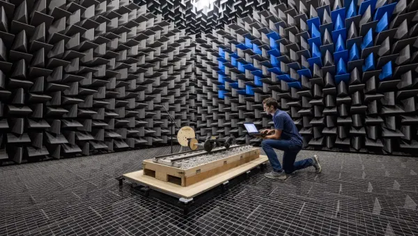
Large reverberation chamber
Construction
- built as a single-skin concrete box
- isolated from the surrounding building and adjacent test chambers
- reinforced concrete walls 305mm thick
- internal surfaces finished with a hard gloss paint to give a high sound reflection coefficient
Dimensions
- non-parallel walls with edge lengths 9.15 metres wide, by 6.25 metres long and 6.10 metres high
- volume: 348 cubic metres
- surface area: 302 square metres
The non-parallel walls and sloping ceiling prevent ‘flutter echoes’ and standing waves, to give a uniform diffuse field within the chamber.
Access
- heavy double doors 1.98 metres wide by 2.42 metres high
- interconnecting doorway or test aperture between the large and small chambers 2.02 metres wide by 2.42 metres high
Sound sources
- electropneumatic sound source, driven by compressed air
- allows noise levels up to 145dB to be generated for high-intensity noise tests
Small reverberation chamber
Construction
The construction is similar to the large chamber.
Dimensions
- non-parallel walls with edge lengths 6.40 metres wide, by 4.60 metres long and 4.30 metres high
- volume: 131 cubic metres
- surface area: 153 square metres
The non-parallel walls and sloping ceiling prevent ‘flutter echoes’ and standing waves, to give a uniform diffuse field within the chamber.
Sound sources
The electropneumatic sound source can be used to generate noise levels up to 160dB.
For lower sound levels we use specialist heavy-duty mid- and high-range loudspeakers and subwoofers.
Transmission suite
Both chambers can be used together as a transmission suite. We can measure transmission losses (noise reduction) of:
- walls
- partitions
- panels
- double- or triple-glazing samples
The wall or other test structure is built within the aperture between the 2 chambers and can be up to 2.0 metres wide by 2.4 metres high. Noise is then generated and measured in one chamber, and the noise transmitted though the test sample is measured in the other chamber.
The drop in sound levels across the test sample enables the transmission loss to be measured in different frequency bands. Similarly the large anechoic and small reverberant chambers can be used where diffuse-field to free-field testing is required.
Control room
There is a control room serving the 2 chambers. Cable ports give access to and from the chambers.
Research
We use the reverberation chambers for University research projects. They're also used for commercial testing and consultancy.
Typical uses include:
- measurement of sound power to British, European and International standards
- measurements of insertion losses of hearing protectors or flight helmets using MIRE (microphone in real ear) or ATF (acoustic test fixture) methods
- high intensity testing of satellite or aircraft components
- measurements of the sound absorption of acoustic tiles, wall coverings or theatre seats
The 2 chambers are used together for measuring the transmission losses of walls, partitions or glazing.
A list of the standards we test to is available at IVSR Consulting.