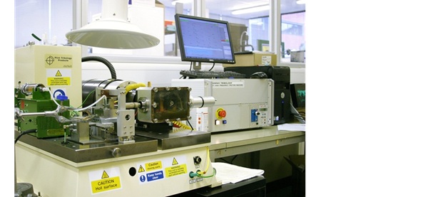
TE77 reciprocating tribometer
Location: Building 7 room 2027
TE77 High Frequency Friction Machine, manufactured by Phoenix Tribology Ltd., is supplied with its own floor standing bench and with integral control unit incorporating a SUPERSLIM Serial Link Interface Module, which is connected to a host PC with COMPEND 2000 sequence control and data acquisition software installed.
The system provides sequence control of load, frequency and temperature plus data acquisition of measured parameters, at both low and high speed.
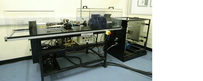
TE74 twin disc/roller tribometer
Location: Building 7 room 2027
The TE 74 Two Roller Machine, manufactured by Phoenix Tribology Ltd., is for the study of traction, wear and rolling contact fatigue under conditions of heavily loaded, lubricated, pure rolling, and rolling and sliding. The machine incorporates two motors, one to provide the input power and one to absorb the transmitted power.
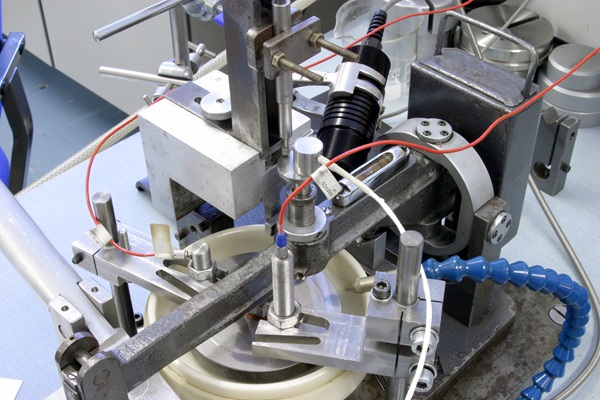
TE66 microabrasion rig
Location: Building 7 room 2023 - Bay 3
The TE 66 Micro-Scale Abrasion Tester, manufactured by Phoenix Tribology Ltd. and conforms to: BS EN 1071-6: 2007
The TE 66 Micro-Scale Abrasion Tester is used for determining the wear coefficient of hard and soft coatings and monolithic materials by abrasive wear, in a ball on plate contact configuration. The machine may also be used as a crater-generating tool on coated surfaces for coating thickness determination.
Samples are typically 20 millimetre (mm) × 30 mm by 3 mm thick.

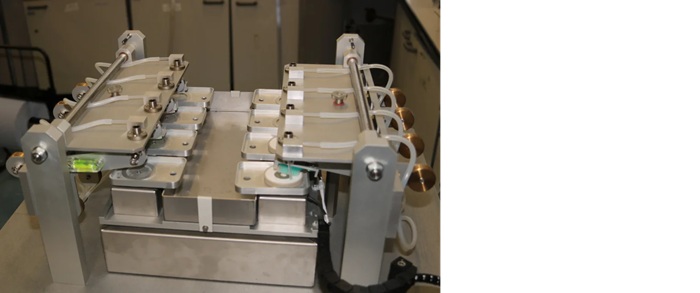
TE85 tooth brushing rig
Location: Building 7 room 2023 - Bay 3
The TE85 Eight Station Orbital Tooth Brushing Rig, manufactured by Phoenix Tribology Ltd., provides circular orbital, elliptical orbital and reciprocating motion, with fixed tooth brush samples loaded against moving teeth samples.
Toothbrushes are cut down for easy attachment to the loading arms.
Pin-on-disc machines
Location: Building 7 room 207 and Building 7 room 2031
nCATS has two pin-on-discs, the first is a low speed machine developed from an abrasive wheel machine that operates at a low-speeds but high torques. Over the year this has been used in various research and consultancy projects from wire line wear, to stone or rock on steel using water-based mud lubricant, to simulate downhole conditions. Electrochemical measurements and polarisation have been used to explore corrosion and to affect friction. The latest project is looking at wheel squeal and brake dust generation.
The second pin-on-disc is a smaller faster version, which can be used for early developments of electrostatic charge measurements in steel-steel and hybrid contacts, later projects explored carbon brakes with the latest work studying polymer brushes.
Mini traction machine (MTM)
Location: Building 30 room 3017
This allows fully automated traction mapping of lubricants under conditions commonly found in internal combustion engines. Additional features allow the measurement of anti-wear additive film growth on test specimens, investigation of soft contacts, reciprocating friction, and wear measurements.
In the standard configuration the test specimens are a 19.05 mm (3/4″) steel ball and a 46 mm diameter steel disc. The ball is loaded against the face of the disc and the ball and disc are driven independently to create a mixed rolling/sliding contact. The frictional force between the ball and disc is measured by a force transducer. Additional sensors measure the applied load and the lubricant temperature.
3D spacer layer imaging (3D-SLIM)
The 3D-SLIM option uses optical interferometry to measure sub-micron additive films on the specimens as they form during the test. To make the measurement the steel test ball is loaded against a glass disc coated with a chromium and silica layer. The contact is illuminated by a white light source directed down a microscope and through the glass disc.
Part of the light is reflected from the chrome layer on the disc and part travels through the silica layer and any additive film, and is reflected back from the steel ball. The recombining light paths form an interference image which is focused onto the imager of a high resolution RGB camera. The camera image is captured by a digital frame grabber and can be analysed by the control software to determine a film thickness map of the contact.
To perform the test, the steel ball is loaded against the steel disc and run under mixed sliding/rolling conditions for a fixed duration. The ball is stopped periodically, loaded in reverse against the glass disc, and a film thickness map of the complete contact area is taken. This allows film thickness measurements to be taken of any reaction films as they form. When used together with the friction measurement, this provides a full, real-time picture of both the chemical and physical effects of the films formed in the contact.
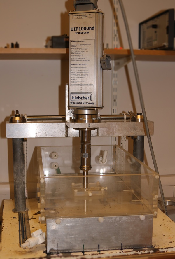
Cavitation erosion rig
Location: Building 13 room 1035
The cavitation erosion rig is custom-built using an ultrasonic horn to induce cavitation bubble creation. The bubbles collapse on the surface, producing a supersonic micro-jet that erodes the surface underneath the horn. This is an “indirect” method of cavitation. The rig complies with ASTM G32, operating at 20 megahertz (MHz) at a displacement of 50 micrometres (µm). Tests can take place in distilled water for pure erosion and salt water for erosion-corrosion experiments.
The rig complies with ASTM G32, operating at 20 kilohertz (KHz) at a displacement of 50µm. The amplitude is set up using a Keyence high-speed, high-accuracy charge-coupled device (CCD) laser displacement sensor.
Cavitation samples are 25 mm squares of 5 mm thickness. Other samples can be accepted with possible adaptation.
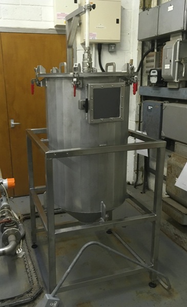
Slurry erosion rig
Location: Building 13 room 1035
The slurry jet erosion rig is driven by a Crest Pumps PPM multistage mechanical seal centrifugal plastic pump. The rig is capable of erosion velocities of up to 30 metres per second (m/s), typically with a sand slurry concentration of 2%, but this concentration can be varied.
Impact velocities up to 24 m/s can be achieved, with discreet impact angles of 15°, 30°, 45°, 60° and 90°. Particle size from sub 100 microns to 2 mm can be used. The rig uses tap water, but other fluids can be handled.
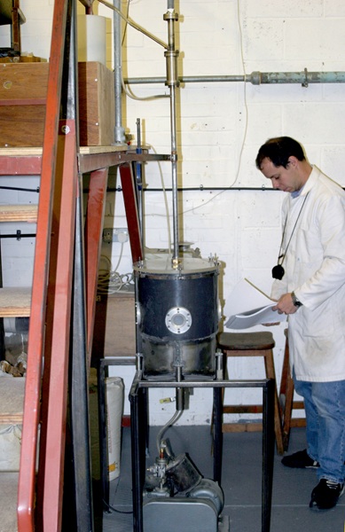
Air-sand erosion rig
Location: Building 13 room 1035
This is a custom-built rig housed in an acoustic chamber, as the high velocities used during operation create a noise hazard.
The rig consists of a compressor air supply that is passed to the test chamber via a flowmeter and then a venture. The venture allows the introduction of the erosive particles (erodents). The feed-rate of these is controlled by a vibratory hopper, and these particles are accelerated at the target sample by the air (and a metre long tube). Impact velocities as low as 30 m/s through to 300 m/s are possible. The most common erodent is silica sand but we have also used alumina, diamond, and glass beads.
Discreet impact angles of 15°, 30°, 45°, 60° and 90°. Particle size from sub 100 microns to 2 mm can be used.
A paper entitled "Design and performance of a high velocity air–sand jet impingement erosion facility" was written when this rig was first build.
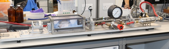
High-velocity impact rig
Location: Building 7 room 2023 - Bay 4
The impact rig was designed at the University of Southampton and manufactured by Safire and Associates.
The is a pneumatic system powered from the air-lines in the laboratory. The line connects to a valve and pressure gauge that controls the pressure in an accumulator. The accumulator stores a volume of air awaiting release by a very-fast acting valve that is electronically opened by a foot pedal.
This is connected to a smooth-bored barrel that makes a near gas-tight seal with the projectile. The barrel is mounted on two gimbal arrangements allowing elevation and direction adjustments. The projectile is a 9 mm diameter ball fired by the sudden release of the gas from the accumulator into the test chamber. Visualisation of the impact is possible, including with a high-speed camera. We are able to record exit velocity from the barrell, and pressure waves form the impact.
The rig has been adapted for various projects, including firing water slugs at over 200 m/s, and using high-speed cameras to examine the impact on a surface.
More technical specification for listed equipment available for internal staff use only. Please contact us to find out more.